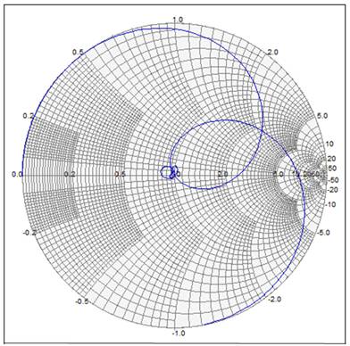
S11 and S22 below, with marker at 5Ghz resonance. Or is the issue just with the way that ADS plots S parameters? Would I expect the same plot on an actual VNA on the Smith chart display.īTW, I'm also including magnitude and phase charts of S11 to show that those reading are behaving as expected. I figured that with S parameters being complex they would normally be plotted on the smith chart, but what I'm seeing doesn't seem to make sense to me. Or, is the Smith chart not appropriate for plotting S parameters? So what is the meaning of the S11 plot on the smith chart? I would expect it to show 0 at resonance. Or, it is defined mathematically as the 1-port. The Smith chart doesn't seem to show the same thing. The Smith chart is a polar plot of the complex reflection coefficient (also called gamma and symbolized by ). Enter Load and Characteristic impedances to calculate VSWR and Reflection Coeffecients. If you have trouble opening PDF files on a Windows system, see the Documentation section of the Advanced Design System Release Notes. These files are formatted and optimized for printing one or more pages. Use the following links to display pdf versions of ADS documentation.
#Smith chart simulator manuals#
You can toggle between Impedance and Admittance charts. Printing Manuals for Advanced Design System. Transform your product pages with embeddable schematic, simulation, and 3D content modules while providing interactive user experiences for your customers. Ladder network, elements are loaded using drag drop method. A free online environment where users can create, edit, and share electrical schematics, or convert between popular file formats like Eagle, Altium, and OrCAD. It uses the advantage of Windows environment to provide friendlier way to simulate Graphical RF designs. QuickSmith was designed to perform a rapid and efficient Smith Chart calculation.
#Smith chart simulator how to#
Looking at the other graphs of S11 and S21, they seem to makes sense, where at 5GHz S21 goes to 0 dB and S11 goes to very low, meaning %100 of the signal from port 1 goes to port 2 as you would expect. Apologies for the poor audio quality - more info belowThis video shows how to use the SimSmith software program to design L matching networks for the same. click anwhere inside the chart to see the corresponding circles. QuickSmith is a Smith Chart based linear circuit simulation program for Microsoft Windows. In the Smith chart below, at resonance, 5GHz, it shows S11 as being ( 1 + i0 ). By my understanding at 5GHz, the input to the filer, S11 should be 0, with maybe a phase change, and also the reflection coefficient should be 0. ONLINE SMITH CHART TOOL Frequency Frequency span ± Characteristic Impedance Permittivity e eff Impedance 50.0 + 0.00j Admittance 0.0200 + 0.00j Reflection Coefficient 0.

My issue that I'm having is interpreting the Smith chart results. It's a simple band-pass, the resonates at 5GHz. To get the feel of it I used the circuit below as a test, and analyzed it. Just to get some practice I'm using Keysite ADS simulator. I'm trying to become reacquainted with microwave circuits and how to analyze them, especially with a VNA.


 0 kommentar(er)
